Updated
6-13-08.
Updated to reflect Revision A Updated
8-11-09.
Add information and revision history Updated
1-20-09. Move Parts List to this page.
SLIM-MXR-3,
Mixer, size-A
Use
your mouse's "right click" and "Save Link" to download:
a.
SKSLIM-MXR-3.sch
Rev A
,
Schematic, in ExpressPCB software.
b.
LAYSLIM-MXR-3.pcb
Rev A,
Layout, in ExpressPCB software.
Use
this drawing to locate
the parts on the SLIM Board.
c. PLSLIM-MXR-3 Parts List.
Maintained only on this page.
d.
PWB-MXR-ADE.pcb
Rev 0,
Base
artwork for PWB, in ExpressPCB software.
Use this drawing to order the pwb from Express. This is the
base
configuration for design of the SLIM-MXR-3.
Click to get full information for a basic mixer design on the PWB-MXR-ADE
page.
The SLIM-MXR-3 was
designed
to be used for the Mixer 3 addition to the MSA
when adding the Tracking Generator.
It was a replica of
SLIM-MXR-1, using the same schematic and parts list. Since
then, SLIM-MXR-3
has been revised and has its own documentation.
J1
is
the Local Oscillator input port. J3 is used as the RF Input
port. J2
is used as the down converted IF output port. For the MSA/TG,
J2
is the Tracking Generator Output, operating from 0 MHz to 1000
MHz. Pin 2 of the ADE-11X
is
connected to its internal diode bridge, which is responsive down to 0
Hz.
This module can be used in other applications, but
it is probably better to use the basic PWB-MXR-ADE
and custom design the components for your specific application.
J1 expects an input level of approximately, +10
dBm. J3
expects an input level of approximately, +10
dBm.
Minicircuits
specify
the
ADE-11X conversion loss at -7.5
dB. I measured the ADE-11X
conversion
loss at -6.5 dB. The output level at J2 should be approximately,
-10 dBm to -12 dBm. I would caution the user that the J2
output
also contains many frequency products, in addition to the expected
0-1000 MHz.
The SLIM-MXR-1
Rev 0 is very easily to upgrade to Rev A.
Revision History Original
Release: Released
7-01-2007
SLIM-MXR-3 Rev 0, using SK-MXR-1 Rev 0, PWB-MXR-ADE Rev 0, PLSLIM-MXR-3
Rev 0
Revision A:
Revised 6-11-08
SLIM-MXR-3
Rev A, SKSLIM-MXR-3 Rev A, PWB-MXR-ADE Rev 0,
PLSLIM-MXR-3 Rev A
1. Added
a 2.5 dB attenuator network in the L
port
path to the
mixer. This provides a better impedance match between the LO
input
connector - J1, and the mixer, which, improves the mixer
isolation.
2.
Added
a 14 dB attenuator network in the
R port path to the
mixer. This provides a better impedance match between the R
input
connector - J3, and the mixer.
3. Added a 2 pF
chip capacitor to the mixer pin 3
junction to ground (C29 position). This helps match the mixer
to
the 14 dB attenuator network and J3.
These
modifications greatly improve the mixer isolation.
But, it makes it necessary for the LO Drive at J1 to be approximately
+9.5
dBm. To use this module as a mid-drive (+7 dBm), the
attenuator
must be
removed.
However, I have tested this module with as
little as
+4.5 dBm at J1
(+2 dBm on
the ADE-11X's L port) with only an additional -1 dB of conversion loss.
Revised 9-08-2008:
errors on Parts
List, revised to PLSLIM-MXR-3
Rev B. No other changes.
SLIM-MXR-3
Rev A, SKSLIM-MXR-3 Rev A, PWB-MXR-ADE Rev 0,
PLSLIM-MXR-3 Rev B
SKSLIM-MXR-3,
Schematic of SLIM-MXR-3
The coupling resistor R15 is a
short circuit (zero ohm resistor), allowing very low frequencies to
pass.
Parts List, PLSLIM-MXR-3 Revision B, 9-8-2008
(updated 1-23-2016) Desig.
Value
Part Number
Digikey
Number
Cost
Notes C5
RevA, deleted
100 pf
C25
RevA, deleted 100 pf
C29 2 pF
CL21C020CBANNNC
1276-2549-1-ND
0.10 was ECJ-2VC1H020C/PCC020CNCT-ND
R1 330
MCR10ERTF3300
RHM330CHCT-ND
0.04 was MCR10EZHF330/RHM330CCT-ND
R5 15
MCR10ERTF15R0
RHM15CHCT-ND
0.04 was MCR10EZHF15.0/RHM15.0CCT-ND
R9 330
MCR10ERTF3300
RHM330CHCT-ND
0.04 was MCR10EZHF330/RHM330CCT-ND
R21 75
MCR10ERTF75R0
RHM75CHCT-ND
0.04 was MCR10EZHF75.0/RHM75.0CCT-ND
R25 120
MCR10ERTF1200
RHM120CHCT-ND
0.04 was MCR10EZHF120/RHM120CCT-ND
R29 75
MCR10ERTF75R0
RHM75CHCT-ND
0.04 was MCR10EZHF75.0/RHM75.0CCT-ND
J1 SMA
optional Molex, 538-73391-0070
WM5544-ND
4.74
J2 SMA
optional Molex,
538-73391-0070
WM5544-ND
4.74
J3 SMA
optional Molex,
538-73391-0070
WM5544-ND
4.74
MXR ADE-11X
ADE-11X
Minicircuits
2.95
R15 0
MCR10EZHJ0.0
RHM0.0ACT-ND
0.08
or use jumper
PWB Circuit Board
PWB-MXR-ADE
3.28
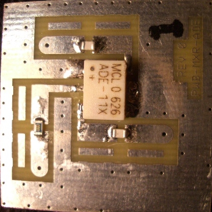
LAYSLIM-MXR-3, Parts
locator for SLIM-MXR-3
The photo was taken before C29 and
attenuators were
added to the
board.