Coaxial Cavity Filter
for
Modularized Spectrum Analyzer
This
Page was Started Dec. 14,
2004 Go B Updated Dec. 28,
2012
This page will act as a design guide for building a Coaxial Cavity
Filter for the Modularized Spectrum Analyzer. This 1st I.F.
filter
is composed of four individual coaxial cavities, cascaded together
using
"hairpin" coupling. Traditionally, coaxial cavity filters are
built
using rectangular shields with aperture coupling. This design is
a change from the "norm" and makes for a very simple construction.
A second filter, on this page, is a two cavity
version. It is used as a tuning filter following a Step Recovery
Diode
Multiplier Module. The dimensions are identical for both filters,
the difference being the number of cavities. Assembly is the
same for both. Both will tune from about 900 MHz to 1050 MHz with
a bandwidth of approximately 2 MHz for the 4 cavity filter and about 4
Mhz for the 2 cavity filter.
The main purpose of this filter is to attenuate
the
second LO (LO 2 = 1 st I.F. + Final Xtal Filter)
and the image frequency, which is 2 times the final xtal frequency
below the commanded center frequency (image = 1 st I.F. + 2x Final Xtal
Filter). Expect an insertion loss of 5 to 8 dB for the 4 cavity
filter and 2 to 4 dB for the 2 cavity filter. Most of the
pictures were taken when the 2 cavity filter was constructed.
A secondary goal of the filter is to attenuate the
response at the pass band of 10.7 MHz., the frequency of the Final I.F.
Best attenuation here is wanted to decrease intermodulation
products from MSA input signals that are 10.7 MHz apart. A
good "rule of thumb" is about -50 dBc.
For more good information on the
construction of a single Coaxial Cavity
Filter, I suggest visiting this link:
www.nippynet.com/QWfilter.pdf. A good build and description by
Mike Suhar, W8RKO.
Coaxial Cavity Dimensions (inches):
1013
MHz Cavity Filter, 2 MHz BW
I admit that construction of this filter looks daunting, but it is
really easy to
build.
I used RG-141 hard pipe for input and output, and its center conductor
for
interstage coupling with
teflon dielectric for spacers. It was "fairly" close to 50 ohms
and had a loss of about 7 dB. Silver plating would improve
insertion loss, but probably not more than 1 dB. However, loss is
not a concern
here. The MSA is not designed for low loss as a goal.
I bought a 24" length of 1 inch copper tubing at Home Depot and
used their pipe
cutter to make 7 pieces, each 3.1 inches long. You will notice
the above dimensions show that the pipe is not exactly 1 inch diameter,
even though, that is
what it is called. The inside diameter is really not that
critical. The only critical lengths are the center
resonators. These coaxial resonators have a characteristic
impedance of 85 ohms.
Use quarter inch copper tubing for the resonators
and cut
each to 3 inches in length. A portion of the stub will protrude
through
the bottom plate, which makes soldering easier. Any excess can be
cut off when the filter is completed.
Use .062 brass for the bottom and top plates and thread the top plate
for the
4-40 tuning
screws. Thicker material would be sturdier, but not
necessary. Drill the bottom plate as per the above
dimensions. A drill press would be nice tool to have. Wish
I had one.
Each cavity wall is drilled to accept RG-141 hard pipe. A 9/64
drill bit is perfect.
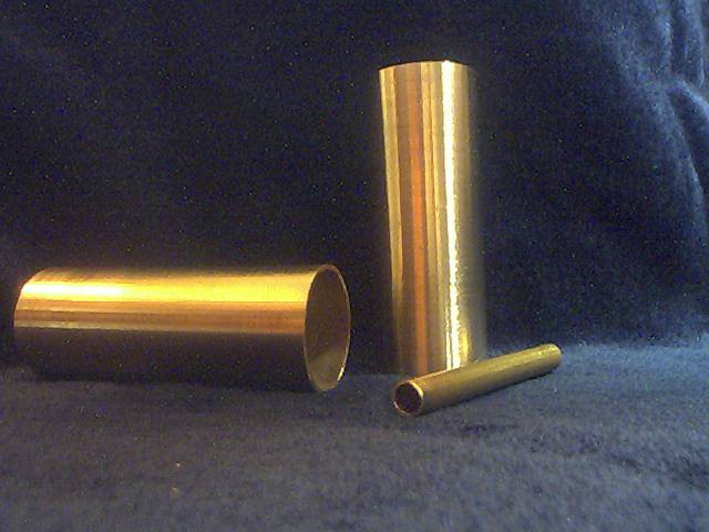
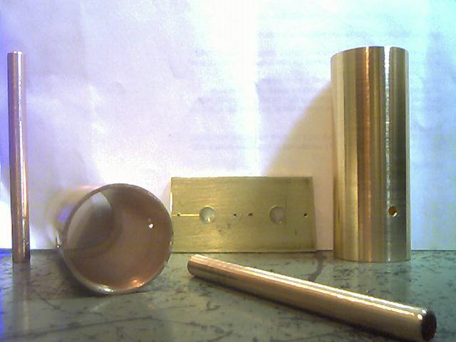
Cut and
polished
Drilled
Pieces fit
These photos were taken during the building of a dual cavity
filter. The 4 cavity filter is cut and drilled the same way.
Once the holes are drilled, clean and polish the
inside and outside of the pipes as best you can. I used emory cloth
wrapped around a piece of foam rubber, stuck on a long drill bit to
polish the inside of the pipe. The cavities are now ready to be
soldered together.
Clamp the 4 pipes side by side, with a wooden dowel
(or a very long drill bit) through all 8 coupling holes for
alignment. The following picture shows the clamping for the two
cavity filter. For 4 cavities, lay them flat and use a larger
clamp. Use a propane torch and solder the pipes together, top to
bottom using regular 60/40 rosin core solder. Let cool and remove dowel
(or what's left of it).
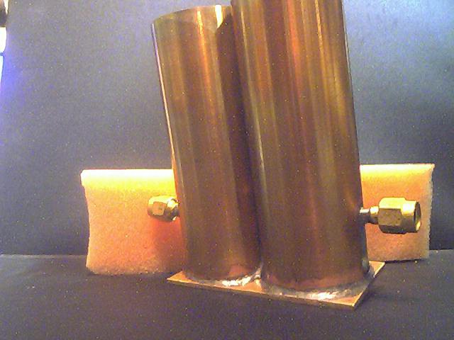
Clamped and ready to solder. Cavities soldered and sitting on bottom
plate
Make the input and output probes. I used SMA
connectors on RG-141, but you can connect the input and output of the
filter directly to the modules if you wish. Either way, use RG-141 as
the drawing shows. Strip off the outer conductor and dielectric leaving
about two
inches of raw center conductor. Bend the center conductor 90 degrees as
shown, wedge the RG-141 into the input and output holes.
Use the center conductor and teflon dielectric from
some RG-141 for the hairpin couplers. Take about a foot of RG-141
and remove the internal center conductor and dielectric. Cut the center
conductor into 3 ea, 4 inch pieces. Cut 19 spacers from the dielectric,
each one about 3/32 inches long. Install the spacers and install the
probes into the cavity as shown. Leave extra length on the probes to
stick out the bottom plate when installed. I suggest you stagger
the extra length on all the probes for easier insertion through the
bottom plate holes. Install the bottom plate and cut off the
excess probe wires. Bend the leads flush to the bottom plate.
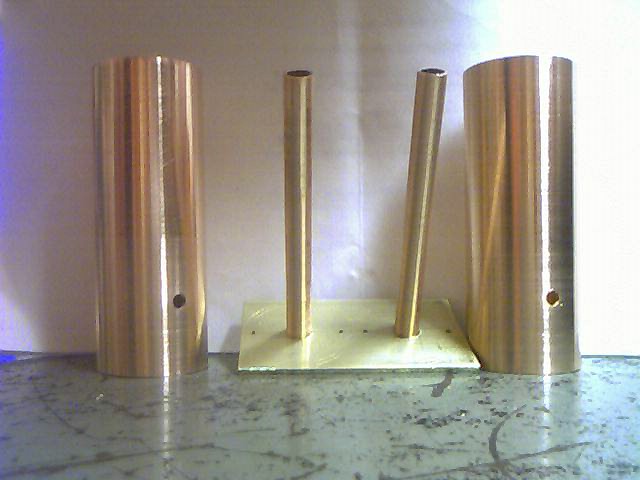
Input and output probes
Interstage installed
Bottom plate positioned
Now, we are ready to solder the bottom plate to the
cavities. Reclamp the cavities together so they won't fall apart
during soldering. Push the 1/4 inch stubs into the bottom plate
leaving a total length of 2.72 inches above the bottom plate (for
tuning to 1013.3 Mhz). This length is not critical but try to
make each stub the same length and make sure they are shorter than the
natural resonant length of 2.81 inches (1013.3 MHz).
Make sure the stubs are centered in each cavity. If, after
soldering, the stubs are not centered, simply insert a drill bit into
the stub and use it to bend the stubs to a centered position.
I suggest using a vice to hold the bottom plate
parallel to ground, leaving enough working space below the assembly to
sweat solder the stubs and probes to the bottom plate.
Use a propane torch and start by soldering the
bottom plate to the cavities. Next, solder the probe wires and stubs to
the bottom plate. Try to keep the torch from directly hitting the
input/output connectors. There will be more than enough indirect heat
for the RG-141 to sweat solder onto the cavities. Let cool and
inspect for a good sweated joint between each cavity pipe and the
bottom plate. The extra stub length below the bottom plate can be
cut
off or left intact. It makes no electrical difference.
Bottom plate soldering complete
I left the top plate for last. Verify the
cavity resonators (stubs) are centered in each cavity. We are now
ready to solder the top plate to the filter assembly. Clamp the
top plate to the filter assembly and solder it to the tops of each
cavity. Without a top plate and tuning screws, this filter will
resonate at approximately 1060 MHz. A top plate without tuning screws
will lower the resonant frequency less than 5 MHz.
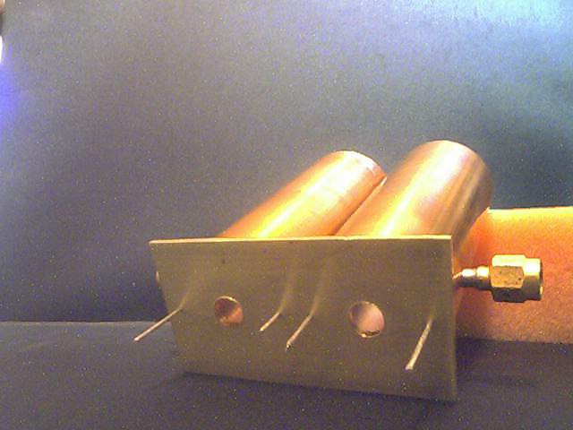
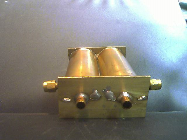
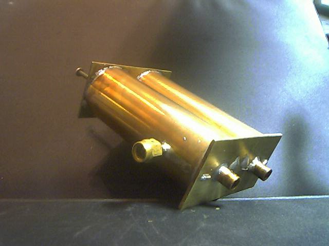
This set of pictures are the completed 2 bank cavity filter:
Bottom
Side and bottom
Side and top
Install the 4-40 tuning screws using a lock washer
and nut. As a starting point before tuning, allow the tuning screws to
extend into the cavity about 0.25 inches. Blob some RTV or some
other "pucky" over the stub holes on the bottom plate. This will help
prevent the internals from tarnishing and corroding, as these are the
only holes exposing the cavities to outside air. You could even stuff a
small package of silica gell "absorbant" into the stubs before
"pucking".
The following pictures are from W4ZCB. His 4
bank filter is a derivation of my specified filter. Notice that
he is using solid resonators rather than hollow 1/4 inch pipe. He
threaded the rods and bottom plate. He does not need tuning
screws for the top plate. Tuning is accomplished by lengthening
or shortening the resonators from the bottom. The nominal length
of each stub resonator will be approximately 2.81 inches at 1013.3
MHz. He has also silver
plated the assembly. How's that for class! The final
assembly (right) is shown without the top cover plate installed.
Tuning the Filter
If you are building this filter for the MSA, you may
tune the filter during the initial Set Up and Calibration of the
MSA. No special test equipment is required. If not, you will need
an appropriate frequency source and detector for tuning. A VNA is a
logical choice.
Alignment results of Coaxial Cavity Filters are
mainly dependent on the physical dimensions of the hairpin
couplers. You
will notice, in the drawing, that a teflon spacer separates the
vertical
portion of the hairpin from the wall of the cavity. You would assume
the distance from the hairpin to the wall is fixed. However, the
length of hairpin conductor between the spacers will allow the it to be
bent a minor amount. If it is bent
closer to the wall, the Filter will exhibit higher insertion loss, with
narrower bandwidth.
If it is bent farther from the wall, the Filter will exhibit lower
insertion loss, with wider bandwidth. Of course, the top plate
cannot be soldered in place if you "tweek" the hairpins. You can
temporarily affix the top plate by using rubber bands to hold it in
place during alignment.
The following is a representation of the minimum and maximum
characteristics of a typical 4 bank, coaxial cavity filter:
One Filter I built has a 3 dB bandwidth of 2.2 MHz, with an insertion
loss of 7.1 dB. The rejection at 1034.7 MHz is -112 dBc.
The following sweep is that of the Coaxial Cavity
Filter built by Jim McLucas for the Verification MSA.
The
Magnitude trace shows
the response of the Cavity
Filter when installed in its final configuration in the MSA. The
frequencies displayed are offset below the
actual frequencies of the Cavity Filter. That is, the center of 0M
corresponds to 1013.3 MHz, the -20M corresponds to 993.3 MHz, and 20M
is 1033.3 MHz. The ultimate rejection is much better than the graph
indication of -88 dBc. The real ultimate rejection cannot be seen due
to the noise floor of the MSA (-110 dBm) masking it. The true response
of the filter is -108 dBc. The attenuation at 1034.3 MHz is not shown
but would be a bit higher than the 20M point. Obviously, it would be as
good or below what is indicated at 20M. The graph also shows that
the response at the 10.7 MHz bandwidth (near the -100 scale line) is
about -78 dBc. This is 28 dB better than the "rule of thumb" design
goal of -50 dBc.