Crystal Ladder Filter Board
PWB-CLF-5
Generic, 5-Pole Filter,
With Applications

PWB-CLF-5,
Crystal Ladder Filter Board, size-A, 1.2 x 1.2 inch square.
   
Download SKPWB-CLF-5.sch, Schematic, in ExpressPCB software.
    Download PWB-CLF-5.pwb, Printed Wiring Board and Layout, in ExpressPCB software.

    The PWB-CLF-5 is a Printed Wiring Board that will accomode up to 5 series crystals.  It is based on a generic design that can generate a variety of filter responses.  The response of a Crystal Ladder Filter depends entirely on the values of components placed on the board.  Therefore, no electrical specifications are assigned to this pwb.  Also, no component values are assigned to this pwb.
    However, I will include, at the bottom of this page, specifications and component values for some different filters.  Each has a different characteristic but uses the same Crystal.  You can use the information as a guide for designing other filters.  I highly recommend going to the AADE web site and downloading their Filter Design and Analysis software.  I created the schematic for this generic board using their ladder component references.  However, I use a different topology for impedance transformation.
    Here is another crystal ladder filter program.  Although limited in its design capability, it is perfect for the PWB-CLF-5 topology.  Very easy to use.  By Horst Steder, DJ6EV and Jack Hardcastle, G3JIR.  To download, go to http://www.arrl.org/qexfiles and find "11x09_Steder-Hardcastle.zip".

Documentation for Generic, 5-pole Crystal Ladder Filter

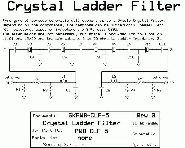
SKPWB-CLF-5. Schematic for Generic, 5-pole Crystal Ladder Filter
CrysFilters/skpwb_clf_5.gif
    There are no component values called out in the schematic.  This is because a variety of filters can be constructed with the same topology, yet have very different operating characteristic.  There is one difference from the AADE topology.  I am using a low-pass impedance transformation (L/C network).

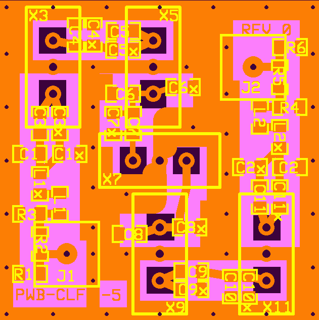
PWB-CLF-5, Master Artwork for Generic, 5-pole Crystal Ladder Filter
CrysFilters/pwb_clf_5.gif
    You will notice extra components, not called out in the schematic.  It is likely that a required component value is not a standard value.  The supplemental (x) components can be added to achieve the proper values.  Not all components are used, depending on the type of Response.  Some are replaced with shorts or zero ohm resistors.

Layout, Parts Placements for Generic, 5-pole Crystal Ladder Filter
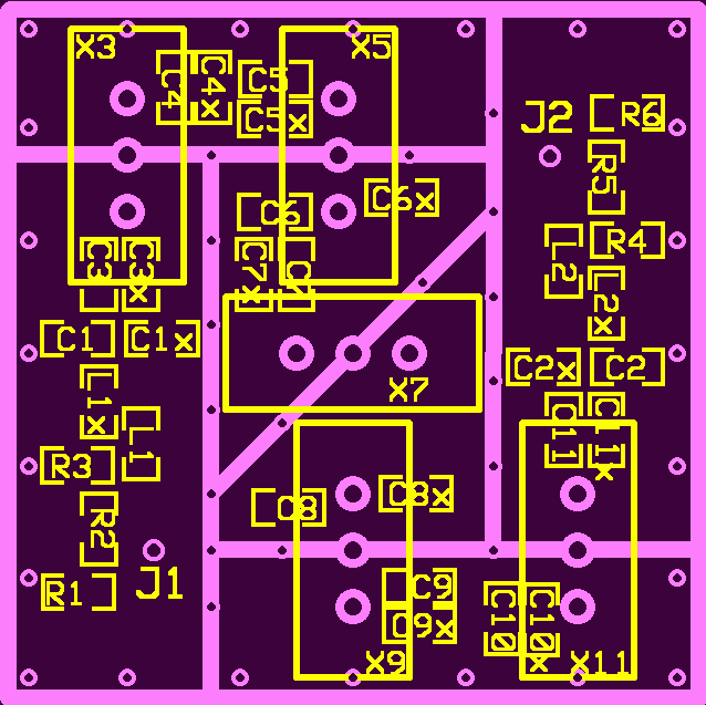
CrysFilters/LayoutParts.gif
    This view shows component placement and fence locations.  The blue lines indicate the fences.  Each section of the filter is isolated from the next section.  This isolation is very important to obtain good Ultimate Rejection Ratio.  You might not see this method of fencing in many radio filters.  For Single Sideband or CW filtering, extremely high rejection is not usually necessary.  The human ear can not discern out-of-band signals that are greater than about 50 dB below the main signal of interest.  However, for a spectrum analyzer, the rejection ratio must be better than 70 dB.  The following screen print shows the fencing without component placements.

Trace Layer for Generic, 5-pole Crystal Ladder Filter, showing Fences
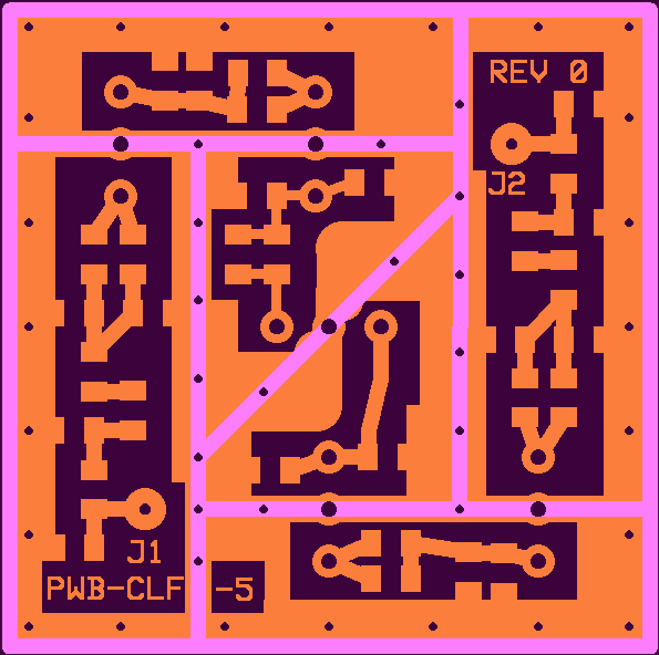
CrysFilters/LayoutFence.gif
    The crystals (X3-11) and the RF connectors (J1, J2) are installed from the bottom side of the board.  The internal fences are installed on the top side of the board, the trace side.  When the module is complete, each section will have its own separate top cover soldered in place.  The perimeter fence should be about .5 inch high and extend below the bottom of the board so that it can be soldered on both sides.  The internal fences should also be .5 inches high.  This will make them extend about .1 inch above the perimeter
fence.  This makes it much easier to cut and install the top covers for each section.
     I recommend using coffee can lids (tin plated steel) for fences and covers.  It can be cut with scissors, although I don't suggest using your wife's sewing scissors.

Bottom Ground Layer, as viewed from the top
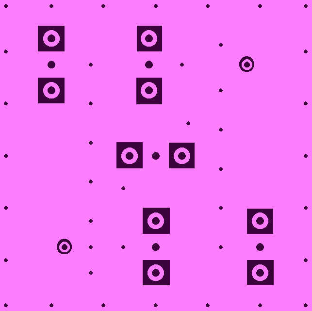
CrysFilters/LayoutMaster3.gif

Construction Hints for Generic, 5-pole Crystal Ladder Filter:
1. Do not install the fences.
2. Install the components on the top side of the board.  Do not install the attenuators.  They will inhibit testing.
3. Install the two connectors on the bottom side of the board.
4. Install the five crystals from the bottom side of the board.
5. Test the filter without variable tuning components.  You should expect very poor Ultimate Rejection Ratio, due to the missing fences.  That is fine.  You are concerned only with S11 Magnitude return loss, and S21 bandpass response.
5a. If the filter has respectable S21 and S11 data, install the internal fences and then install the perimeter fence.  Test the filter again to verify the S11 and S21 data has not changed much.  Expect a minor amount of S11 Magnitude return loss change.  Install the individual top covers.
5b. If the filter has poor response, change the components to variable components, or you can try adding small amounts of capacitance across the fixed capacitors to change the response.  This is not the best way to tune a filter because you can add capacitance, but you cannot subtract capacitance.


Results of a Specific Crystal Ladder Filter Design
    The following are results of a Crystal Ladder Filter I designed and constructed, using the PWB-CLF-5.   I have given it a preliminary part number of SLIM-CLF-10.11/1.0  The Crystals used are 10.11 MHz, and the design bandwidth goal was 1.0 KHz.  For actual filter component values, see the Table at the bottom of the page.  These are the average motional characteristics of the 5 crystals, PN: N10.11 PDI.
Fs = 10.11099705 MHz, Fp = 10.12984 MHz, Lm = 20.83468 mH, Cm = .0119 pF, Rm = 10.97 ohms, Cp = 3.182 pF.  The 5 crystals were selected from a batch of 85 that were close in Fs (10 Hz) and Rm (2 ohms).

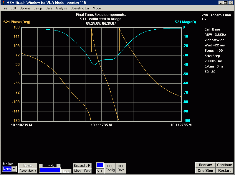
S21 plot of completed SLIM filter with shields in place, showing -3dB points
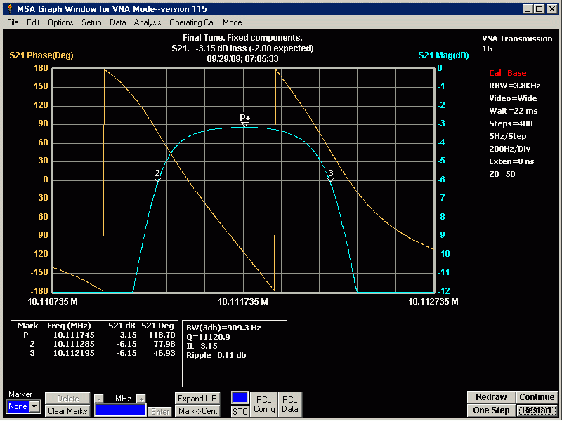
CrysFilters/1KHzAsBuiltS21final.gif
    The response is Butterworth, with the 3 dB points indicating the bandwidth is 909 Hz, narrower than the 1.0 KHz design.  Since this filter is built with fixed, high tolerance components, the 10% bandwidth error is not unusual.  In-band ripple is excellent.  The center frequency is higher than the 10.11 MHz specification of the crystals.  This is always the case when designing crystal ladder filters.  The calculated loss with the AADE software is -2.31 dB.  I calculated a bit more loss to be -2.88 dB.  The actual loss is -3.15 dB.  I attribute the difference to my use of "lossy" ceramic capacitors, low Q inductors, and minor differences in the crystals' Rm (2 ohms).  I suggest using high quality microwave capacitors, but I didn't have any.  I can certainly live with this performance.

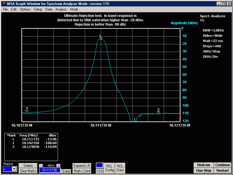
Graph of completed SLIM filter, showing slope and ultimate rejection
CrysFilters/1KHzAsBuiltrejection.gif

    Disregard the in-band response of this plot, although the peak level is accurate.  The previous plot shows the quality of the in-band response much more accurately.  The important information in this graph is the amount of base line noise present outside of the filter skirts.  This is the ultimate rejection ratio.  We would like to have a crystal filter that has a rejection of at least -70 dBc.  Best would be rejection of -90 dBc or better.  This filter is showing excellent rejection, better than -94 dBc.  To obtain this rejection, the completed module must be well shielded, including interstage shielding.  More information is given in the construction section of this page.  The noise floor of this VNA is about -123 dBm.  The dramatic "dip" at 4 KHz above the center frequency is due to the combined parallel resonance of the crystals and parasitic capacitance of the pwb.

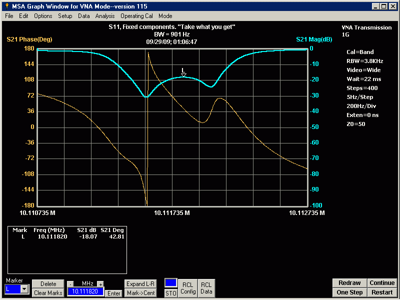
S11 plot of completed
SLIM filter, showing showing return loss.
CrysFilters/1KHzAsBuiltS11final.gif
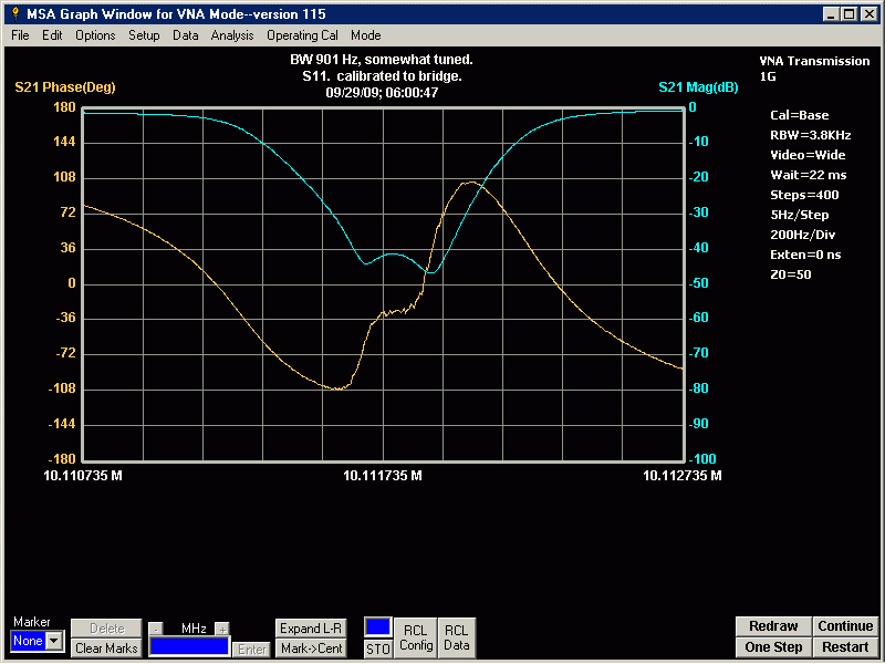
    This plot is S11 measurements of the filter, although the Graph Scale references are S21.  Technically this is measuring the S21 of a Reflection Bridge.
   
A well designed filter should have at least -30 dBc return loss at center frequency.  This filter is indicating better than -30 dBc.  In reality anything better than -20 dBc is pretty good for a home-brew filter.  This plot is a result of fine tuning the filter with adjustable components and substituting them with fixed, surface mount components.  I suggest this technique of substituting fixed components for variable ones.  Variables are usually quite large which makes shielding difficult.

Other plots of SLIM-CLF-1.0
    The following graphs are taken with the same filter, but with some differences that are explained.
S11 Untuned, preliminary, before components finalized.
CrysFilters/1KHzAsBuiltS11.gif
    This plot is S11 measurements of the filter, although the Graph Scale references are S21.
    This plot was taken after constructing the filter using the components called out in the design.  No tuning was performed.  The return loss is about -18 dB.  To some, this might seem to be rather poor.  However, this filter is quite useable the way it is.  See the next plot for S21.

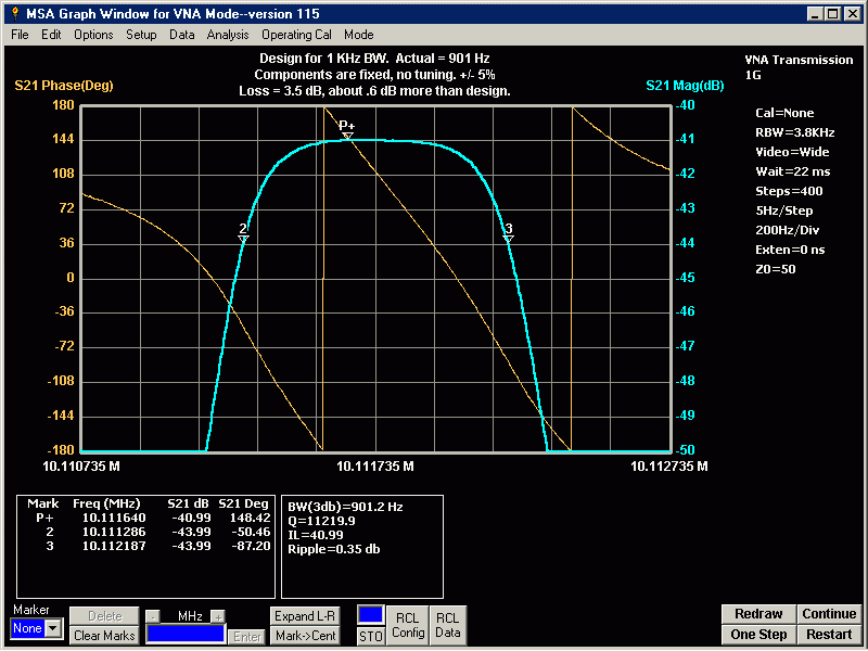
S21 Untuned, preliminary, before components finalized.
CrysFilters/1KHzAsBuiltS21.gif
    This untuned filter is showing more insertion loss than when in its final form.  It is 3.5 dB, compared to 3.15 dB for a tuned filter.  The bandpass response is still, quite good.  I do not show a skirt response and ultimate rejection plot, simply because there is very little difference from the final plots.

S11 Tuned, preliminary, before components finalized.
CrysFilters/1KHzAsBuiltS11Tuned.gif
    This plot is S11 measurements of the filter, although the Graph Scale references are S21.
    This plot is the response of the filter with variable tuning components in place.  It has been tuned for best return loss.  The next step is to remove the variable components and replace them with fixed components.  I will not show an S21 plot here.  The insertion loss and slope is identical to the S21 plot at the beginning of this page.  However, the ultimate rejection ratio is poor due to the variable components acting like "antennas".  Actually, I didn't spend much time tuning this filter.  With some fine "tweeking" it could be improved a little more.  But, once -30 dBc return loss is achieved, any better is a waste of time.  This is indicating better than -40 dB.

  The following table is presented with component values for Butterworth Response filters, using the same crystal PN: N10.11 PDI.  S is a short or zero ohm resistor, NI means the component is not installed.  BW = bandwidth.  ZL= crystal ladder impedance (what the LC matching network is transforming 50 ohms to).  Design = values in AADE software.  Actuals = actual results or actual values installed in tested filter.

Design
*Actuals
Design
Actuals


BW, Hz
1113
909.3
1350
1145


Loss, dB
-2.31 dB
-3.15 dB
-2.4 dB
-2.7 dB


ZL, ohm
235.75

279.98


R1, ohm
NI
NI NI NI


R2, ohm S
S
S
S


R3, ohm NI NI NI NI


R4, ohm NI NI NI NI


R5, ohm S
S
S
S


R6, ohm NI NI NI NI


L1, uH
1.517 1.59
1.688
1.65


L2, uH
1.517
1.49
1.688
1.65


C1, pf
128.7 127
120.58
121


C2, pf 128.7 123
120.58
121


C3, pf 194.4 200
163.73
164


C4, pf 108.1 105.6
91.0
91


C5, pf S
S
S
S


C6, pf 194.4 200
163.73 164


C7, pf 243.34
270
S
S


C8, pf 194.4 200
163.73 164


C9, pf S
S
S
S


C10, pf 108.1 105.6
91.0
91


C11, pf 194.4 200
163.73 164


*Actuals.  These are the results and values for the preliminary part number, SLIM-CLF-10.11/1.0
The blanks are left open for future designs.
    A parts list is not released and I do not intend to release one.  The reason for this is that for a fixed component filter to be accurate, the capacitors would have to be better than 1% tolerance.  This would make the unit extremely expensive.  I sugguest buying 5% or 10% NPO capacitors in quantity (cheap), and select-in-test.  For example, if you need a 194.4 pf capacitor, you test a batch of 150 pf, 33 pf, and 10 pf and select three that add closest to 194.4 pf.  The pwb has pads for two parallel capacitors at each pole, and more can be "piggybacked".  In reality, a large batch of the following should give you an assortment of combinations that will get you to within 1% of the value you need.  (in pfd): 3.3, 10, 22, 33, 47, 82, 100, 150, 200, 240, 300, 390, 470, 680).  Split each value into two brands, say Murata and Panasonic (or your favorite company).  The reason: Digikey may give you 100 of a value that are from the same lot-date-code and the values will not vary more than .1%.  This is where you want "sloppy" values.  Only two characteristics are important when combining capacitors to make a single value: the total combined value (in pf) and they MUST be NPO (COG).  Otherwise, temperature changes will make the filter worthess.
  If you do not have the capability to test capacitors, then you must obtain 1% capacitors.  Or, wait until your MSA and Tracking Generator is complete (with another Final Filter).  Then use the MSA/TG to test capacitors.

A Computer Analysis of a Crystal Ladder filter, using matched crystals
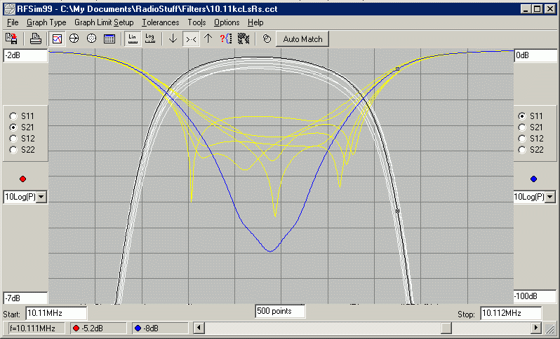
The following is a computer generated analysis of a filter that is built with a typical set of "matched" crystals.  The crystals are matched to within 50 Hz and their motional resistance to within 2 ohms.
CrysFilters/xtalspred.gif
The black and white traces are S21 insertion loss and the blue and yellow traces are S11 Return loss.  The black and blue are when the
motional characteristics for each crystal are identical (perfectly matched).  The white and yellow indicate the filter response with random crystal frequency (Fs) and motional resistance (Rs) variations.  Fs is changing up to +/- 25 Hz and Rs is changing up to +/- 1 ohm.
    The insertion loss is deviating about .3 dB (scale = .5 dB/div).  The return loss is deviating over 50 dB (scale = 10 dB/div), but it still remains better than -20 dB.  The bandwidth is deviating as much as 70 Hz at the 3 dB marker on the graph (200 Hz/div).  It is difficult to discern the white traces at the -3 dB point and the bandwidth deviation is more likely no greater than the 50 Hz deviation of the crystals.
    This analysis indicates that matching 5 crystals for Fs and Rs will result in a very good Crystal Ladder Filter.  As a matter of fact, this is a worse case analysis and does not show results if the ladder matching capacitors are "tweeked" for best performance.