Modularized Spectrum Analyzer
You may have
become
familiar with the MSA, which is presented on the Main Page. This is a guide for
adding a
tracking generator to the 0 to 1000 MHz Modularized Spectrum
Analyzer. Two designs are presented. The original tracking
generator design is shown first, followed by the new TG design.
This Page was Started Aug. 17, 2006. The Original Tracking Generator information was removed from the main page and put here.
Updated Sept. 12, 2006. The New Tracking Generator is advised if the builder is planning to evolve his MSA into a VNA.
Updated Sept. 21, 2006 Updated block diagrams to include integrated amplifiers within the VCO modules.
What is a Tracking Generator?
A tracking generator (TG) is an RF signal generator that will change frequency at the same rate as the Spectrum Analyzer (SA). When the SA is commanded to look for a particular frequency, the TG output frequency will be that same frequency.
Here is the basic MSA Block Diagram :
Block Diagram of Basic MSA
This is the same Block Diagram as the one on the main page for the MSA. All construction information for the basic MSA is presented on the Main Page.
The frequency agile oscillator is LO 1. VCO 1 will tune from 1013.3 MHz (which corresponds to a 0 MHz input signal) to 2013.3 MHz (which corresponds to a 1000 MHz input signal). The input signal is mixed with VCO 1 to create a difference frequency of 1013.3 MHz. This 1st IF signal is tightly filtered by the cavity filter and then presented to the second mixer. Here, it is mixed with the VCO 2 (1024 MHz) to create the final IF of 10.7 MHz. The final IF is amplified and filtered and presented to the Log Detector for power to voltage conversion. The Log Det output voltage is sent to the Analog to Digital converter to be read by the PC. The basic MSA will read absolute Magnitude (power) measurements vs. frequency. A signal reference is required to perform Magnitude gain/loss measurements. A Tracking Generator makes a useful signal reference.
Original Tracking Generator
Block diagram of the MSA with the added Original Tracking Generator, highlighted.:
Block Diagram of MSA/TG (original)
LO 3, which is the combination of PLL 3 and VCO 3, creates a fixed frequency. It is the same frequency of LO 1 when the MSA is commanded to "0" MHz. In this case, the frequency is 1013.3 MHz. As LO 1 is increased in frequency, the Tracking Generator output is the difference frequency of LO 1 and LO 3. Since LO 1 tunes from 1013.3 to 2013.3 MHz, the TG output is 0 to 1000 MHz, thereby, "tracking" the MSA. There is also a sum frequency output of the Mixer 3, which is 2026.6 MHz to 3016.3 MHz. A low pass filter is integrated into Mixer 3, to attenuate the sum frequencies. It is labeled as a 1000 LPF, but with the suggested components, the actual 3 dB point is about 1300 MHz. The TG output level of -30 dBm is determined by the output level of VCO 3 and the amount of attenuation in the path. In the above diagram, the attenuation is -37 dB. Higher TG output level can be obtained, but with higher interference.
The VCO 1 module is shown with an internal amplifier, feeding Mixer 3. If the VCO 1 module does not have the dual amplifier capability, an external amplifier must be added.
This is a very simple topology for a tracking generator. However, it does have the drawback of potential interference.
Since the LO 3 frequency is fixed at 1013.3 MHz, the signal can get back into the MSA I.F. chain and cause interference. It can be significant if the design and construction is not optimum. Here is how the signal will interfere, using some component assumptions:
The Log Detector is LM3356. 0 dBm is the saturation input level to the log det. It's minimum detectable signal is -90 dBm. Any signal that is not of interest (SNOI) at this point, and greater than -90 dBm, is deemed "interference".
The I.F. Amplifier has 44 dB of gain.
The other MSA chain elements (mixers and filters) have a total loss of -24 dB.
The total gain of the MSA chain is +20 dB (+44 -24); therefore, the input dynamic range of the MSA is -20 dBm to -110 dBm.
Assuming Mixer 1 has a -7 dB conversion loss, the total gain from Mixer 1 R port to the Log Det is +27 dB. Therefore, a 1013.3 MHz signal (-117 dBm), at the R port output of Mixer 1, will create a -90 dBm level at the input to the Log. Detector. A signal from the TG's LO 3 that reaches Mixer 1, R port, and is greater than -117 dBm, is considered a SNOI and will interfere with real signal measurement.
Now let us follow the 1013.3 MHz signal that is created by the TG's VCO 3. It has an initial power level of +13 dBm. It passes through the 37 dB attenuator to become a level of -24 dBm.
Mixers are ADE-11X, and have only 25 dB of isolation (data sheet). Therefore, the -24 dBm SNOI at the R port of Mixer 3, passes to the L port at a level of -49 dBm. The SNOI then passes through the 6 dB attenuator and is on the output of the VCO 1 module, with a level of -55 dBm. The VCO amplifiers have about 25 dB of reverse isolation. Therefore the SNOI is -80 dBm on the output of the VCO 1 module. The SNOI then travels into Mixer 1 module, through the 6 dB attenuator. The SNOI level at the L port of Mixer 1 is now -86 dBm. The isolation of the ADE-11X is -25 dB, therefore, the SNOI at the R port of Mixer 1 is -111 dBm. This level of -111 dBm will create a signal level of -84 dBm at the input to the Log. Det. This is 6 dB above the interference level of -90 dBm, and interference will result. What the display will look like, is, the noise floor of the Graph will rise by 6 dB. The input dynamic range will be degraded by 6 dB, resulting in an input dynamic range of -104 dBm to -20 dBm. In many cases this is not significant. The MSA still has an 84 dB dynamic range, a 6 dB degradation.
When I first designed and buit the SSA Prototype with this tracking generator, there was no interference problem in this area. I was using the Watkins Johnson, W1J, which has 40 dB of isolation. When designing the next version, the SSA Board, I chose the ADE-11X because the mfg claimed at least 40 dB isolation. Well, in reality, their 40 dB number is a "best case" data point and, not where we operate this mixer, at 1013 MHz.
I have seen the ADE-11X isolation range from -18 dB to -28 dB in the 3 units I have. If the isolation is as poor as -18 dB, then the above calculations would degrade another 14 dB (7dB x 2 mixers). With this case, the SNOI would be -97 dBm at the R port of Mixer 1. This would create a signal level of -70 dBm at the input to the Log Det. This is a 20 dB degradation to the dynamic range. Not only are the mixers not guaranteed to have a specific isolation value, the Pill style amplifiers cannot guarantee -25 dB isolation. Poor layout and "leaky" connections can also contribute to degraded isolation.
Here is another significant interference from the VCO 3's 1013.3 MHz, "SNOI": It will travel through Mixer 3, from the R port to the I port. Numerically, the -24 dBm SNOI at the Mixer 3 R port will be -49 dBm at the I port. This SNOI is only 19 dB lower than the TG output's signal of interest of -30 dBm. In many cases, this is not of concern. For example, tuning of filters, where the filter under test will attenuate this 1013.3 MHz, SNOI. But, if a wide band amplifier or a mixer is the test subject, then significant intermodulation (IMD) can result. There is a low pass filter on the output of the TG, but it's purpose is to attenuate harmonically generated spurs from Mixer 3. It will not attenuate the 1013.3 Mhz. A notch filter would work well here, but TG frequencies in the 900 MHz area would be degraded.
To decrease the interference in both examples, the Trk Gen output can be lowered from -30 dBm to a value that causes the least interference. The -37 dB attenuator could be changed to a -47 dB attenuator. The SNOI interference would decrease by 10 dB in both cases. The best method of reducing the interference is to choose a mixer 1 and mixer 3 that have the highest possible isolation at 1013 MHz.
PLL 3 is operated in a fixed frequency mode, and it's phase detector frequency (PDF) must be chosen so that the "N" steps of the PLL will be a sub-multiple of the LO 3 frequency. This PDF will probably be very low, resulting with a high phase noise LO 3. This is not important as a tracking generator with the MSA. The main consideration is getting the correct frequency for LO 3. In the above examples, the frequency is 1013.3 MHz. This frequency is determined by the frequency of LO 2 and the center frequency of the Final Xtal Filter (1024 MHz - 10.7 MHz = 1013.3 Mhz). The PDF of PLL 3 could be 100 KHz. But, the attractive point of the Basic MSA is, any Final Frequency Filter can be used. What if the Final Xtal Filter were 9.954 MHz, with a bandwidth of 2 KHz? The Tracking Generator's LO 3 must be tuned to: 1024 - 9.954 = 1014.046 MHz. The obvious PDF would be 1 KHz. However, most Integer-N PLL chips can not divide that high (1014.046 / .001 = 1,014,046). For sure, the LMX 2326 cannot. A very clever way to overcome this shortfall is to use a PDF that is not quite so obvious. Since this is a fixed frequency LO, it doesnt need to step to any other required frequency. Use a PDF that is a numeric sub-multiple of both the output frequency and the Master Clock Frequency. In the above block diagram, the master clock is 64 MHz. What PDF will be a numeric sub-multiple of both 1014.046 MHz and 64 MHz ? With some mathmatics involved, a PDF of .070098576 MHz will (closely) meet the requirements. The PLL's divide by N counter will be 14466 (1014.046 MHZ / 14466 = 70,098.57597 Hz) and the divided by R counter will be 913 (64 MHz / 913 = 70,098.57612 Hz). The two frequencies are not exactly the same. They are .00345 Hz different. Using the following formula the output frequency of the LO 3 is calculated : VCO = (clock/R) x N or (64 MHz/913) x 14466. This equals 1014,046,002.19 Hz. This is 2.19 Hz higher than the wanted 1014.046 MHz. However, 2 Hz is well within the bandpass of 2 KHz, the BW of the Final Xtal Filter. The actual output frequency of the Tracking Generator will always be off by 2.19 Hz. The PLL 3 can be designed with a loop filter for a PDF of 70 KHz. This 2 Hz offset will not be a factor when tuning filters, or for gain/loss measurements. As long as the final I.F. frequency is within the bandpass of the Final Xtal Filter, all is well. This also holds true when this Tracking Generator is used with the MSA/VNA, which is discussed on a separate page.
If a Fractional-N PLL is used for PLL 3, there is the same consideration of tuning LO 3 for the correct frequency. But, a Fractional-N PLL will have a PDF that is 16 times it's step frequency. If a step size of 1 KHz is required, the PDF will be 16 KHz, and this is easily accomplished with the LMX 2350 or LMX 2353.
Here are some suggested loop component values for the original PLL 3, for different PDF's.
PLL 3 Used as Icp PDF C1 R1 C2 R2 C3
ADF 4112 IntegerN 5.0 ma 5 KHz 120 nf 620 1.5 uf 1.1 K 47 nf
LMX2350/53 IntegerN 1.6 ma 5 KHz 39 nf 2.0 K .47 uf 3.6 K 15 nf
LMX2326 IntegerN 1.0 ma 5 KHz 27 nf 3.0 K .27 uf 5.6 K 8.2 nf
LMX2325 IntegerN 5.0 ma 10 KHz 68 nf 620 .68 uf 1.1 K 22 nf
ADF 4112 IntegerN 5.0 ma 10 KHz 68 nf 620 .68 uf 1.1 K 22 nf
LMX2350/53 IntegerN 1.6 ma 10 KHz 22 nf 2.0 K .22 uf 3.6 K 6.8 nf
LMX2326 IntegerN 1.0 ma 10 KHz 12 nf 3.0 K .15 uf 5.6 K 4.7 nf
LMX2350/53 FractionN 1.6 ma 80 KHz 2.7 nf 2.0 K 27 nf 3.6 K 820 pf
Notice that the LMX2350 and LMX2353 can be operated as a Fractional-N PLL. This allows the PDF to run at a higher frequency, and yet, step in 5 KHz increments.
Click here to see a schematic of PLL 2 using the LMX 2353.
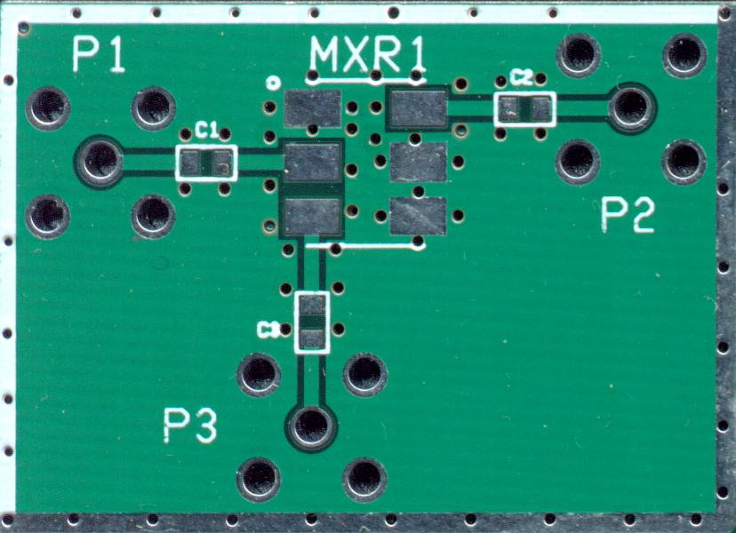
Here is a schematic and suggested values to build Mixer 3. It can be built on the Generic Mixer Module Board. The mixer can be an ADE-11X or a suitable mixer with the same footprint. Resistor values are shown for 6 dB, 16 dB, and 37 dB pads.
Here is a schematic and suggested values for an amplifier with an integrated high pass filter.
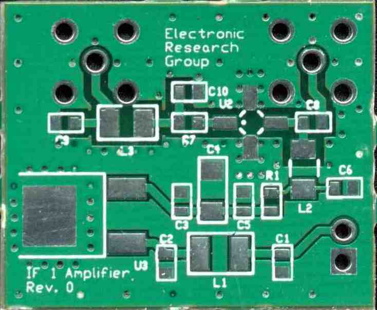
This amplifier should have an average gain of +20 dB from 800 Mhz to 2000 Mhz, and should saturate with an output of +13 dBm. 5 volt operation is not a necessity. The 30 ohm bias resistor can be changed for other voltage regulators. The SGA-4586 is a suggestion, and a variety of other amplifiers will work well. Shown, is a single stage amplifier board that Cash Olsen has produced. It has room on the input for a resistive attenuator or a pass filter.
The PLL 3 Module is identical to the MSA's PLL 2 module and can be seen on the main page. Likewise, the VCO 3 Module is identical to the MSA's VCO 2 Module.
New Tracking Generator
Block diagram of the MSA with the New Tracking Generator, highlighted:
Block Diagram of MSA/TG (new)
This Page was Started Aug. 17, 2006. The Original Tracking Generator information was removed from the main page and put here.
Updated Sept. 12, 2006. The New Tracking Generator is advised if the builder is planning to evolve his MSA into a VNA.
Updated Sept. 21, 2006 Updated block diagrams to include integrated amplifiers within the VCO modules.
What is a Tracking Generator?
A tracking generator (TG) is an RF signal generator that will change frequency at the same rate as the Spectrum Analyzer (SA). When the SA is commanded to look for a particular frequency, the TG output frequency will be that same frequency.
Here is the basic MSA Block Diagram :
Block Diagram of Basic MSA
This is the same Block Diagram as the one on the main page for the MSA. All construction information for the basic MSA is presented on the Main Page.
The frequency agile oscillator is LO 1. VCO 1 will tune from 1013.3 MHz (which corresponds to a 0 MHz input signal) to 2013.3 MHz (which corresponds to a 1000 MHz input signal). The input signal is mixed with VCO 1 to create a difference frequency of 1013.3 MHz. This 1st IF signal is tightly filtered by the cavity filter and then presented to the second mixer. Here, it is mixed with the VCO 2 (1024 MHz) to create the final IF of 10.7 MHz. The final IF is amplified and filtered and presented to the Log Detector for power to voltage conversion. The Log Det output voltage is sent to the Analog to Digital converter to be read by the PC. The basic MSA will read absolute Magnitude (power) measurements vs. frequency. A signal reference is required to perform Magnitude gain/loss measurements. A Tracking Generator makes a useful signal reference.
Original Tracking Generator
Block diagram of the MSA with the added Original Tracking Generator, highlighted.:
Block Diagram of MSA/TG (original)
LO 3, which is the combination of PLL 3 and VCO 3, creates a fixed frequency. It is the same frequency of LO 1 when the MSA is commanded to "0" MHz. In this case, the frequency is 1013.3 MHz. As LO 1 is increased in frequency, the Tracking Generator output is the difference frequency of LO 1 and LO 3. Since LO 1 tunes from 1013.3 to 2013.3 MHz, the TG output is 0 to 1000 MHz, thereby, "tracking" the MSA. There is also a sum frequency output of the Mixer 3, which is 2026.6 MHz to 3016.3 MHz. A low pass filter is integrated into Mixer 3, to attenuate the sum frequencies. It is labeled as a 1000 LPF, but with the suggested components, the actual 3 dB point is about 1300 MHz. The TG output level of -30 dBm is determined by the output level of VCO 3 and the amount of attenuation in the path. In the above diagram, the attenuation is -37 dB. Higher TG output level can be obtained, but with higher interference.
The VCO 1 module is shown with an internal amplifier, feeding Mixer 3. If the VCO 1 module does not have the dual amplifier capability, an external amplifier must be added.
This is a very simple topology for a tracking generator. However, it does have the drawback of potential interference.
Since the LO 3 frequency is fixed at 1013.3 MHz, the signal can get back into the MSA I.F. chain and cause interference. It can be significant if the design and construction is not optimum. Here is how the signal will interfere, using some component assumptions:
The Log Detector is LM3356. 0 dBm is the saturation input level to the log det. It's minimum detectable signal is -90 dBm. Any signal that is not of interest (SNOI) at this point, and greater than -90 dBm, is deemed "interference".
The I.F. Amplifier has 44 dB of gain.
The other MSA chain elements (mixers and filters) have a total loss of -24 dB.
The total gain of the MSA chain is +20 dB (+44 -24); therefore, the input dynamic range of the MSA is -20 dBm to -110 dBm.
Assuming Mixer 1 has a -7 dB conversion loss, the total gain from Mixer 1 R port to the Log Det is +27 dB. Therefore, a 1013.3 MHz signal (-117 dBm), at the R port output of Mixer 1, will create a -90 dBm level at the input to the Log. Detector. A signal from the TG's LO 3 that reaches Mixer 1, R port, and is greater than -117 dBm, is considered a SNOI and will interfere with real signal measurement.
Now let us follow the 1013.3 MHz signal that is created by the TG's VCO 3. It has an initial power level of +13 dBm. It passes through the 37 dB attenuator to become a level of -24 dBm.
Mixers are ADE-11X, and have only 25 dB of isolation (data sheet). Therefore, the -24 dBm SNOI at the R port of Mixer 3, passes to the L port at a level of -49 dBm. The SNOI then passes through the 6 dB attenuator and is on the output of the VCO 1 module, with a level of -55 dBm. The VCO amplifiers have about 25 dB of reverse isolation. Therefore the SNOI is -80 dBm on the output of the VCO 1 module. The SNOI then travels into Mixer 1 module, through the 6 dB attenuator. The SNOI level at the L port of Mixer 1 is now -86 dBm. The isolation of the ADE-11X is -25 dB, therefore, the SNOI at the R port of Mixer 1 is -111 dBm. This level of -111 dBm will create a signal level of -84 dBm at the input to the Log. Det. This is 6 dB above the interference level of -90 dBm, and interference will result. What the display will look like, is, the noise floor of the Graph will rise by 6 dB. The input dynamic range will be degraded by 6 dB, resulting in an input dynamic range of -104 dBm to -20 dBm. In many cases this is not significant. The MSA still has an 84 dB dynamic range, a 6 dB degradation.
When I first designed and buit the SSA Prototype with this tracking generator, there was no interference problem in this area. I was using the Watkins Johnson, W1J, which has 40 dB of isolation. When designing the next version, the SSA Board, I chose the ADE-11X because the mfg claimed at least 40 dB isolation. Well, in reality, their 40 dB number is a "best case" data point and, not where we operate this mixer, at 1013 MHz.
I have seen the ADE-11X isolation range from -18 dB to -28 dB in the 3 units I have. If the isolation is as poor as -18 dB, then the above calculations would degrade another 14 dB (7dB x 2 mixers). With this case, the SNOI would be -97 dBm at the R port of Mixer 1. This would create a signal level of -70 dBm at the input to the Log Det. This is a 20 dB degradation to the dynamic range. Not only are the mixers not guaranteed to have a specific isolation value, the Pill style amplifiers cannot guarantee -25 dB isolation. Poor layout and "leaky" connections can also contribute to degraded isolation.
Here is another significant interference from the VCO 3's 1013.3 MHz, "SNOI": It will travel through Mixer 3, from the R port to the I port. Numerically, the -24 dBm SNOI at the Mixer 3 R port will be -49 dBm at the I port. This SNOI is only 19 dB lower than the TG output's signal of interest of -30 dBm. In many cases, this is not of concern. For example, tuning of filters, where the filter under test will attenuate this 1013.3 MHz, SNOI. But, if a wide band amplifier or a mixer is the test subject, then significant intermodulation (IMD) can result. There is a low pass filter on the output of the TG, but it's purpose is to attenuate harmonically generated spurs from Mixer 3. It will not attenuate the 1013.3 Mhz. A notch filter would work well here, but TG frequencies in the 900 MHz area would be degraded.
To decrease the interference in both examples, the Trk Gen output can be lowered from -30 dBm to a value that causes the least interference. The -37 dB attenuator could be changed to a -47 dB attenuator. The SNOI interference would decrease by 10 dB in both cases. The best method of reducing the interference is to choose a mixer 1 and mixer 3 that have the highest possible isolation at 1013 MHz.
PLL 3 is operated in a fixed frequency mode, and it's phase detector frequency (PDF) must be chosen so that the "N" steps of the PLL will be a sub-multiple of the LO 3 frequency. This PDF will probably be very low, resulting with a high phase noise LO 3. This is not important as a tracking generator with the MSA. The main consideration is getting the correct frequency for LO 3. In the above examples, the frequency is 1013.3 MHz. This frequency is determined by the frequency of LO 2 and the center frequency of the Final Xtal Filter (1024 MHz - 10.7 MHz = 1013.3 Mhz). The PDF of PLL 3 could be 100 KHz. But, the attractive point of the Basic MSA is, any Final Frequency Filter can be used. What if the Final Xtal Filter were 9.954 MHz, with a bandwidth of 2 KHz? The Tracking Generator's LO 3 must be tuned to: 1024 - 9.954 = 1014.046 MHz. The obvious PDF would be 1 KHz. However, most Integer-N PLL chips can not divide that high (1014.046 / .001 = 1,014,046). For sure, the LMX 2326 cannot. A very clever way to overcome this shortfall is to use a PDF that is not quite so obvious. Since this is a fixed frequency LO, it doesnt need to step to any other required frequency. Use a PDF that is a numeric sub-multiple of both the output frequency and the Master Clock Frequency. In the above block diagram, the master clock is 64 MHz. What PDF will be a numeric sub-multiple of both 1014.046 MHz and 64 MHz ? With some mathmatics involved, a PDF of .070098576 MHz will (closely) meet the requirements. The PLL's divide by N counter will be 14466 (1014.046 MHZ / 14466 = 70,098.57597 Hz) and the divided by R counter will be 913 (64 MHz / 913 = 70,098.57612 Hz). The two frequencies are not exactly the same. They are .00345 Hz different. Using the following formula the output frequency of the LO 3 is calculated : VCO = (clock/R) x N or (64 MHz/913) x 14466. This equals 1014,046,002.19 Hz. This is 2.19 Hz higher than the wanted 1014.046 MHz. However, 2 Hz is well within the bandpass of 2 KHz, the BW of the Final Xtal Filter. The actual output frequency of the Tracking Generator will always be off by 2.19 Hz. The PLL 3 can be designed with a loop filter for a PDF of 70 KHz. This 2 Hz offset will not be a factor when tuning filters, or for gain/loss measurements. As long as the final I.F. frequency is within the bandpass of the Final Xtal Filter, all is well. This also holds true when this Tracking Generator is used with the MSA/VNA, which is discussed on a separate page.
If a Fractional-N PLL is used for PLL 3, there is the same consideration of tuning LO 3 for the correct frequency. But, a Fractional-N PLL will have a PDF that is 16 times it's step frequency. If a step size of 1 KHz is required, the PDF will be 16 KHz, and this is easily accomplished with the LMX 2350 or LMX 2353.
Here are some suggested loop component values for the original PLL 3, for different PDF's.
PLL 3 Used as Icp PDF C1 R1 C2 R2 C3
ADF 4112 IntegerN 5.0 ma 5 KHz 120 nf 620 1.5 uf 1.1 K 47 nf
LMX2350/53 IntegerN 1.6 ma 5 KHz 39 nf 2.0 K .47 uf 3.6 K 15 nf
LMX2326 IntegerN 1.0 ma 5 KHz 27 nf 3.0 K .27 uf 5.6 K 8.2 nf
LMX2325 IntegerN 5.0 ma 10 KHz 68 nf 620 .68 uf 1.1 K 22 nf
ADF 4112 IntegerN 5.0 ma 10 KHz 68 nf 620 .68 uf 1.1 K 22 nf
LMX2350/53 IntegerN 1.6 ma 10 KHz 22 nf 2.0 K .22 uf 3.6 K 6.8 nf
LMX2326 IntegerN 1.0 ma 10 KHz 12 nf 3.0 K .15 uf 5.6 K 4.7 nf
LMX2350/53 FractionN 1.6 ma 80 KHz 2.7 nf 2.0 K 27 nf 3.6 K 820 pf
Notice that the LMX2350 and LMX2353 can be operated as a Fractional-N PLL. This allows the PDF to run at a higher frequency, and yet, step in 5 KHz increments.
Click here to see a schematic of PLL 2 using the LMX 2353.
Here is a schematic and suggested values to build Mixer 3. It can be built on the Generic Mixer Module Board. The mixer can be an ADE-11X or a suitable mixer with the same footprint. Resistor values are shown for 6 dB, 16 dB, and 37 dB pads.
Here is a schematic and suggested values for an amplifier with an integrated high pass filter.
This amplifier should have an average gain of +20 dB from 800 Mhz to 2000 Mhz, and should saturate with an output of +13 dBm. 5 volt operation is not a necessity. The 30 ohm bias resistor can be changed for other voltage regulators. The SGA-4586 is a suggestion, and a variety of other amplifiers will work well. Shown, is a single stage amplifier board that Cash Olsen has produced. It has room on the input for a resistive attenuator or a pass filter.
The PLL 3 Module is identical to the MSA's PLL 2 module and can be seen on the main page. Likewise, the VCO 3 Module is identical to the MSA's VCO 2 Module.
New Tracking Generator
Block diagram of the MSA with the New Tracking Generator, highlighted:
Block Diagram of MSA/TG (new)